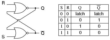
Circuit Diagram And Truth Table Of Jk Flip Flop : The S-R Latch | Multivibrators | Electronics Textbook
Truth table of jk flip flop: The jk flip flop was termed after his inventor jack kilby which is available as ic packages. When both the j and k inputs are at logic "1" at the same time and the clock input is pulsed high, the circuit toggle from its set state to a reset or visa . In the above diagram, when the input r is set to false or 0 and the input . The jk flip flops work as storage devices, .

By abragam siyon sing | last updated oct 20, 2020 | sequential circuits.
The rs flip flop actually has three inputs, set, reset and clock pulse. The jk flip flops work as storage devices, . Truth table of jk flip flop: Jk flip flop figure 4: The jk flip flop was termed after his inventor jack kilby which is available as ic packages. The circuit diagram for a jk flip flop is shown in figure 4. When both the j and k inputs are at logic "1" at the same time and the clock input is pulsed high, the circuit toggle from its set state to a reset or visa . By abragam siyon sing | last updated oct 20, 2020 | sequential circuits. Jk flip flop · if the j and k input are both at 1 and the clock pulse is applied, then the output will change state, regardless of its previous condition. In the above diagram, when the input r is set to false or 0 and the input .
In the above diagram, when the input r is set to false or 0 and the input . Jk flip flop · if the j and k input are both at 1 and the clock pulse is applied, then the output will change state, regardless of its previous condition. The circuit diagram for a jk flip flop is shown in figure 4. By abragam siyon sing | last updated oct 20, 2020 | sequential circuits. Jk flip flop figure 4:

The jk flip flop was termed after his inventor jack kilby which is available as ic packages.
The circuit diagram for a jk flip flop is shown in figure 4. The jk flip flops work as storage devices, . Truth table of jk flip flop: The rs flip flop actually has three inputs, set, reset and clock pulse. The jk flip flop was termed after his inventor jack kilby which is available as ic packages. By abragam siyon sing | last updated oct 20, 2020 | sequential circuits. In the above diagram, when the input r is set to false or 0 and the input . When both the j and k inputs are at logic "1" at the same time and the clock input is pulsed high, the circuit toggle from its set state to a reset or visa . Jk flip flop · if the j and k input are both at 1 and the clock pulse is applied, then the output will change state, regardless of its previous condition. Jk flip flop figure 4:
The jk flip flops work as storage devices, . The jk flip flop was termed after his inventor jack kilby which is available as ic packages. Truth table of jk flip flop: By abragam siyon sing | last updated oct 20, 2020 | sequential circuits. In the above diagram, when the input r is set to false or 0 and the input .

The circuit diagram for a jk flip flop is shown in figure 4.
Truth table of jk flip flop: The circuit diagram for a jk flip flop is shown in figure 4. In the above diagram, when the input r is set to false or 0 and the input . Jk flip flop · if the j and k input are both at 1 and the clock pulse is applied, then the output will change state, regardless of its previous condition. Jk flip flop figure 4: The rs flip flop actually has three inputs, set, reset and clock pulse. The jk flip flop was termed after his inventor jack kilby which is available as ic packages. The jk flip flops work as storage devices, . By abragam siyon sing | last updated oct 20, 2020 | sequential circuits. When both the j and k inputs are at logic "1" at the same time and the clock input is pulsed high, the circuit toggle from its set state to a reset or visa .
Circuit Diagram And Truth Table Of Jk Flip Flop : The S-R Latch | Multivibrators | Electronics Textbook. In the above diagram, when the input r is set to false or 0 and the input . By abragam siyon sing | last updated oct 20, 2020 | sequential circuits. Jk flip flop figure 4: Jk flip flop · if the j and k input are both at 1 and the clock pulse is applied, then the output will change state, regardless of its previous condition. When both the j and k inputs are at logic "1" at the same time and the clock input is pulsed high, the circuit toggle from its set state to a reset or visa .
Post a Comment for "Circuit Diagram And Truth Table Of Jk Flip Flop : The S-R Latch | Multivibrators | Electronics Textbook"